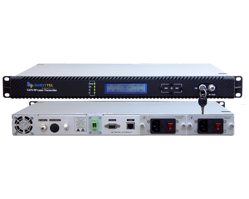
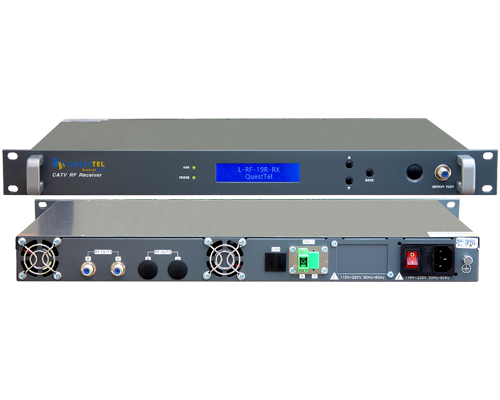
L-RF-19R-RX
CATV RF Optical Receiver 1310-1550 nm 45-862/1003 MHz
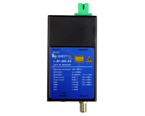
This is our latest high-end two-way output CATV network Fiber Optics Receiver. The L-RF-19R-RX is used to convert a fiber optic connection to RF (coax output). This module able to receive optical signals in either 1310nm or 1550nm. The second optical receiver adds further redundancy. QuestTel's CATV Fiber Optic receivers are designed high reliability with optical AGC (Optical Automatic Gate Control), high level RF output, ease of use, easy to read LED indicators, and suitable for high-level applications. The parameters will be displayed by singlechip to make the engineering debug more convenient.
- High response PIN photoelectric conversion tube.
- Optimizing circuit design, SMT production process, optimizing the whole signal path, makesthe photoelectronic signal transmission more fluent.
- Professional RF attenuation chips, good RF attenuation and equilibrium linear, high precision.
- GaAs amplifier device, power doubly output, high gain and low distortion.
- Able to receive optical signals in either 1310nm or 1550nm
- Dual optical recievers with automatic swtiching
- Singlechip controls the whole work, digital display the parameters, easy and intuitive operation,and stable performance.
- Excellent AGC characteristic, when the input optical power range is -9 +2dBm, the outputlever remain unchanged, CTB and CSO basically unchanged.
- Reserved the data communication interface, can connect the Ethernet transponder, access to thenetwork management system.
| Optical Parameters - RX | |
| Wavelength | 1310 - 1600 nm |
| Receive Optical Power | -9 ~ +2 dBm |
| Optical Return Loss | >45 dB |
| Optical Connector Type | SC/APC / (FC/APC) or specified by the user |
| Fiber Type | Single Mode / Multi Mode - Optional |
| Link Parameters | |
| Transmit Channel | PAL-D/60CH NTSC/80CH |
| C/N | ≥ 51 (-2dBm Input dB) |
| C/CTB | ≥ 65 dB |
| C/CSO | ≥ 60 dB |
| RF Parameters | |
| Frequency Range | 45 - 862 /1003 MHz |
| Flatness in Band | ±0.75 dB |
| Rated Output Level | ≥ 108 dBμV |
| Max Output Level | ≥ 114 dBμV |
| Output Return Loss | ≥14 dB |
| Output Impedance | 75 Ω |
| Electrical control EQ range | 0 - 10 dB |
| Electrical control ATT range | 0 - 20 dB |
| General Parameters | |
| Network Managment | RJ45 & RS232 Supports I.E. & SNMP |
| Power Supply | 90~265VAC -48VDC optional(30~60VDC) |
| Power Consumption | ≤ 30 VA |
| Operating Temperature | -40~60°C |
| Storage Temperature | -40~65°C |
| Relative Humidity | Max 95% no condensation |
| Dimension | 483 x 345 x 44 mm |

Disclaimer: Products, specifications and data are subject to change without notice, to improve reliability, function, design or otherwise.
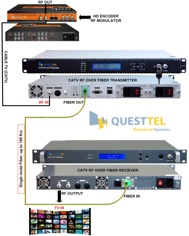
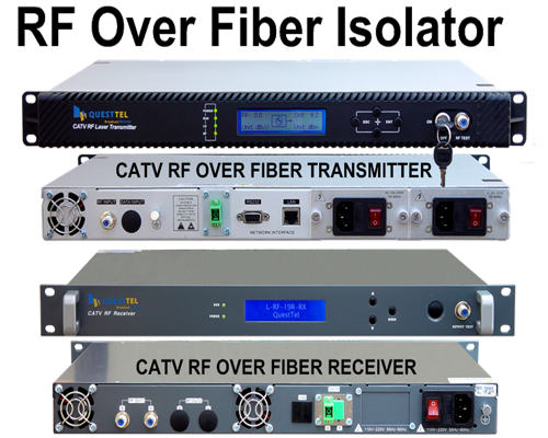
How RF over Fiber Links Work
Converting RF signals into light, then transporting the optical signal over fiber optic cable, is a complex process which requires a high degree of technical expertise. Incoming RF signals from the antenna or signal source are fed into QuestTel's RF over Fiber Transmitter Module via the 75 Ohm RF connector. The Module contains RF signal conditioning and provides complex impedance matching between 75 Ohm input impedance and the Laser, Laser Control, APC, Monitoring and Alarm electronics. The Transmitter Module utilizes an Intensity Modulation scheme to convert RF signals into light. This modulated light is then transported through an optical fiber to the QuestTel's RF over Fiber Optical Receiver Module. The Receiver Module converts the modulated light back into an RF signal. The recovered RF signal is again complex impedance matched and amplified before it becomes available at the output of the Receiver Module.
QuestTel shall have no liability for any error or damage of any kind resulting from the use of this document.