

Short Answer
L-band over fiber converts the 950–2150 MHz signal from a satellite LNB into light, sends it down single-mode fiber, and converts it back to RF for your satellite receivers. Use it instead of coax on long runs (RG-6 already loses 21–32 dB at 100 m), when you need lightning and ground isolation, on routes with electrical interference, or when one dish has to feed several buildings.
Updated November 1, 2026 · Kit figures from QuestTel product data
How L-Band Over Fiber Works
Signal path with the QuestTel kit. RF travels left to right. LNB power comes from the transmitter at the dish. Swipe the drawing to see the full path.
- The LNB on the dish shifts the satellite downlink to L-band, 950–2150 MHz.
- A short coax carries that RF to the fiber transmitter. The transmitter's AGC manages an RF input of 55–78 dBµV.
- The RF modulates a 1550 nm DFB laser. Nothing is demodulated, so the whole block crosses the link: every transponder the LNB delivers.
- One strand of single-mode fiber carries the light to the receiver. The link runs in one direction only.
- The receiver converts the light back to 75 Ω RF on an F connector for your satellite receivers (IRDs), directly or through a splitter.
The kit passes 45–2600 MHz, so the same link also carries off-air channels. See the ATSC channel center frequency table for those frequencies.
Coax vs Fiber: Loss Over Distance
RG-6 figures below are scaled from the Belden 1694A datasheet: 6.3 dB/100 ft at 1000 MHz and 9.8 dB/100 ft at 2250 MHz, which bracket most of the L-band. Fiber figures use 0.25 dB/km at 1550 nm and 0.35 dB/km at 1310 nm. All are cable only, with no connectors.
| Run | RG-6, 1000 MHz | RG-6, 2250 MHz | RG-11 | Single-mode, 1550 nm | Single-mode, 1310 nm |
|---|---|---|---|---|---|
| 100 m | 20.7 dB | 32.2 dB | TODO | 0.025 dB | 0.035 dB |
| 500 m | 103 dB | 161 dB | TODO | 0.125 dB | 0.175 dB |
| 1 km | 207 dB | 322 dB | TODO | 0.25 dB | 0.35 dB |
| 10 km | 2,067 dB | 3,215 dB | TODO | 2.5 dB | 3.5 dB |
Past about 100 m, a coax run usually needs line amplifiers, and each one adds noise. The 500 m and longer coax figures show scale; nobody builds those runs. The fiber figures are optical dB, so double them to compare with coax: 10 km at 1550 nm is 2.5 dB optical, or about 5 dB of RF.
L-Band Link Budget Calculator
Enter your fiber path to get total loss and received optical power with the QuestTel kit: 10 mW (+10 dBm) out, and a receiver range of −13 to +1 dBm.
Example: 1 km at 1550 nm, 2 connectors, 2 splices, no splitter
Above the receiver range by 7.55 dB
Add at least 7.55 dB of attenuation at the receiver. About 14.55 dB would put it mid-range, at −6 dBm.
Total loss = (1 km × 0.25 dB/km) + (2 × 0.5 dB) + (2 × 0.1 dB) + 0 dB = 1.45 dB
Received power = +10 dBm − 1.45 dB = +8.55 dBm
The formula
Total loss (dB) = (length km × fiber dB/km) + (connectors × 0.5) + (splices × 0.1) + splitter loss
Received power (dBm) = +10 dBm − total loss
The link is inside the receiver range when −13 dBm ≤ received power ≤ +1 dBm
Typical values used: fiber 0.35 dB/km at 1310 nm and 0.25 dB/km at 1550 nm; 0.5 dB per connector; 0.1 dB per splice; splitters 3.5 dB (1x2), 7 dB (1x4) and 10.5 dB (1x8). Measure a real link with a power meter before you commission it.
Worked examples
| Path at 1550 nm | Total loss | Received | Result |
|---|---|---|---|
| 1 km, 2 connectors, 2 splices | 1.45 dB | +8.55 dBm | Too much light. Add at least 7.55 dB. |
| 16 km (10 miles), 2 connectors, 4 splices | 5.40 dB | +4.60 dBm | Too much light. Add at least 3.60 dB. |
| 1 km, 1x4 splitter, 4 connectors, 2 splices | 9.45 dB | +0.55 dBm | Inside the range, near the top. |
| 10 km, 1x8 splitter, 4 connectors, 2 splices | 15.20 dB | −5.20 dBm | Inside the range. |
| 80 km, 2 connectors, 16 splices | 22.60 dB | −12.60 dBm | Inside, but only 0.40 dB above minimum. |
| 120 km, 2 connectors, 24 splices | 33.40 dB | −23.40 dBm | Too little light by 10.40 dB. Ask about the 120 km option. |
LNB Power and Polarity Switching
On a coax install, the satellite receiver sends DC and the 22 kHz tone up the cable to the LNB. Fiber breaks that path: glass doesn't carry DC, and this link runs one way. So the transmitter at the dish feeds the LNB through its F connector instead, at 13/18 VDC, 350 mA max, with 22 kHz tone supported.
| Setting | What it does | When to use it |
|---|---|---|
| 13 VDC | Powers the LNB and selects vertical (or right-hand circular) polarity. | The transponders you need are on that polarity. |
| 18 VDC | Powers the LNB and selects horizontal (or left-hand circular) polarity. | The transponders you need are on that polarity. |
| 0 V (off) | No DC from the transmitter. The kit ships set to 0. | Something else powers the LNB, such as a SWM power inserter or a powered splitter port. Also use it with a passive off-air antenna, which doesn't need DC. |
| 22 kHz tone | On a universal Ku-band LNB, the tone selects the high band and no tone selects the low band. | You need the high band of a universal LNB. Ask QuestTel how the tone is set on your unit. |
- Check the current. The limit is 350 mA. Confirm your LNB's draw on its datasheet before you commission.
- One polarity and band per link. The receivers can't switch the LNB over this link, so every receiver sees the same block. For more than one block, run one kit per LNB output, or use a single-wire (SWM) LNB that puts what the tuners need on one coax.
- Turn off the receiver's LNB power if your IRD has that setting. Nothing on its side of the fiber uses it.
- Protect the units at the dish. The kit is for indoor use, so mount the transmitter in a weatherproof enclosure, with AC power nearby for its 18 VDC supply.
- Ground the dish anyway. Fiber isolates the buildings from each other. It doesn't protect the dish end, so ground the dish and mast to code. The datasheet points to Section 810 of the National Electrical Code.
Common L-Band Over Fiber Setups
Single dish to a headend
LNB to transmitter at the dish, one strand of fiber, receiver in the headend, then coax to the IRDs. One kit carries one LNB output, so count outputs first. Most point-to-point runs under about 30 km need an attenuator at the receiver. The link budget calculator gives the minimum value.
Dish on a roof, far from the equipment room
The dish goes where it has a clear view of the sky, and the receivers stay 300 m away in a basement. RG-6 would lose about 62 to 96 dB on that run. Fiber loses under 0.1 dB. Mount the transmitter in a weatherproof enclosure on the roof, bring AC power for its supply, and take single-mode fiber down the riser. With 2 connectors and 2 splices, that path arrives at about +8.7 dBm, so fit at least 8 dB of attenuation.
One dish feeding several buildings
Put an optical splitter after the transmitter and run one fiber to a receiver in each building. The kit includes one receiver, so each extra building needs another. The splitter costs 3.5 dB (1x2), 7 dB (1x4) or 10.5 dB (1x8). With a 1x4 and 1 km legs, each receiver sees about +0.55 dBm.
Run the calculator for the nearest and the farthest building. The nearest may still need an attenuator on its leg, and the farthest must stay above −13 dBm. QuestTel's rack-mount SC/APC splitters are the 1x2 fiber PLC splitter, 1x4 fiber PLC splitter and 1x8 fiber PLC splitter. For a worst-case design, use the maximum loss on their product pages. See fiber optic couplers for how splitting works.
Hotel or MDU distribution
Fiber gets L-band from the dish to the headend room. From there you have two common routes. Keep L-band and feed set-top receivers through satellite splitters or a SWM splitter, in which case the number of tuners on the SWM LNB is the limit. Or receive the channels at the headend and re-modulate them for the building's coax, using an HDMI RF modulator for each channel.
If L-band stays on coax, budget the RF. The receiver puts out 63–88 dBµV, depending on optical input. A 2-way satellite splitter typically costs 4 to 5 dB at L-band. Many satellite tuners accept about −65 to −25 dBm, which is about 44 to 84 dBµV on 75 Ω. Check the datasheet for your IRD. To run RF over fiber to several buildings below 1 GHz instead, use the CATV fiber network planner.
Troubleshooting
Measure first. A fiber power meter at the receiver's SC/APC input tells you which row you're in. The target is −13 to +1 dBm.
| Symptom | Likely cause | Fix |
|---|---|---|
| No signal, no lock | LNB has no power: the kit ships with the feed set to 0. | Set the transmitter to 13 or 18 V, and measure the voltage at the LNB end of the coax. |
| No signal, no lock | Red status light on the transmitter. It means optical power is high or no RF is detected. | Check the coax from the LNB, then check the RF level against the 55–78 dBµV input window. |
| No signal, no lock | No light at the receiver: a break, a wrong patch, or a dirty connector. | Meter the receiver input. Clean and inspect each connector, then test the strand. See tests on fiber optic cable. |
| Weak signal, low quality, pixelation | Received power near −13 dBm. Each optical dB lost costs about 2 dB of RF. | Clean connectors, look for tight bends, remove a splitter stage. See effects of bending on fiber. |
| Weak signal, low quality, pixelation | SC/UPC connector mated to the kit's SC/APC, or a patch cord with the wrong polish. | Use SC/APC throughout: green connectors, not blue. See fiber connector types. |
| Weak signal, low quality, pixelation | Too much RF splitting after the receiver, or LNB level below 55 dBµV at the transmitter. | Measure RF at the IRD and at the transmitter input. Reduce splitting or amplify the L-band. |
| Overloaded receiver: errors on a short, clean link | Too much optical power. Anything above +1 dBm is out of range, which is normal on runs under about 30 km. | Fit an in-line SC/APC attenuator at the receiver, sized with the link budget calculator. See fiber optical attenuators. |
| LNB not switching polarity | The receiver's 13/18 V command can't cross the one-way fiber. The LNB stays on the transmitter's setting. | Set the voltage at the transmitter for the polarity you need. For both polarities, use one kit per LNB output or a SWM LNB. |
| LNB not switching polarity | The voltage isn't reaching the LNB: an inline device blocks DC, or the LNB draws more than 350 mA. | Measure 13 and 18 V at the LNB. Remove inline devices and check the LNB's current on its datasheet. |
Recommended Equipment
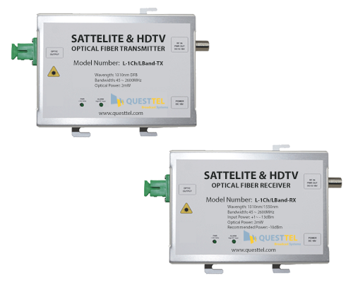
L-Band Over Fiber Link Transmitter and Receiver kit
Model L-1Ch-L-Band-RG-TX/RX
$1,450.00
See the L-1Ch-L-Band-RG-TX/RX kit| Frequency | 45–2600 MHz |
|---|---|
| Transmitter | 1550 nm DFB, 10 mW optical output |
| Receiver | 1290–1600 nm, input −13 to +1 dBm |
| Distance | Standard up to 10 miles; optional 20/40/80/120 km (specify when ordering) |
| RF input | 55–78 dBµV with AGC |
| RX output | 88 dBµV at 0 dB optical input, 63 dBµV at −12 dB |
| LNB power | 13/18 VDC, 350 mA max; 22 kHz tone supported |
| Connectors | F-type female RF, SC/APC optical |
| Fiber | Single-mode, single strand |
| CNR | TX 40 dB / RX 45 dB |
| IMD | 40 dB |
| Impedance | 75 Ω |
| Power | 3.5 W each; TX 18 VDC, RX 12 VDC supplies included |
| Environment | Indoor use |
Related links
- L-Band RF over Fiber Link TX/RX (L-1Ch-L-Band-TX/RX): the related model. Its product page lists 1310 nm and 2 mW (+3 dBm), so subtract 7 dB from the calculator's received power for that unit.
- 1 Channel L-Band over Fiber datasheet (PDF): lists the 1310 nm, 2 mW model and a 12-mile default reach. For the RG kit, use the specs above.
- Contact QuestTel to specify a long-reach option or check a design.
Frequently Asked Questions
How far can L-band go over fiber?
The standard kit runs up to 10 miles. Optional builds run 20, 40, 80 or 120 km, and you specify the option when ordering. Whatever the distance, the received power has to land between −13 and +1 dBm, so check your path with the link budget calculator.
Single-mode or multimode?
Single-mode. The kit uses one strand of single-mode fiber with SC/APC connectors. See singlemode and multimode fiber for the differences.
Can I pass LNB power over fiber?
No. Fiber carries light, not DC. The transmitter at the dish feeds the LNB 13 or 18 VDC, up to 350 mA, so you need AC power at the dish end for its supply. LNB power and polarity switching covers the settings.
Do I need a 10 MHz reference?
This kit doesn't support one. No 10 MHz reference appears in its specs, and its passband starts at 45 MHz. Most TV LNBs run on an internal oscillator and don't need a reference. If yours does, feed it from a local source at the dish.
How many receivers can I feed?
As many as the RF level allows after splitting. One link carries one LNB output, and the receiver puts out 63–88 dBµV for you to split with satellite-rated splitters. All receivers share the same polarity and band unless you use a SWM LNB, which limits you to the number of tuners it supports.
What connectors does the kit use?
F-type female for RF, on 75 Ω coax, and SC/APC for fiber. APC connectors are angle-polished and green. Don't mate them with blue SC/UPC. See fiber connector types.

