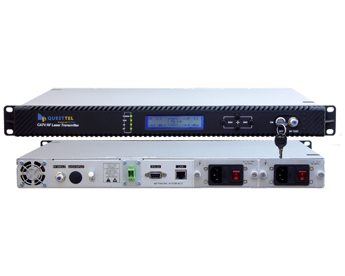
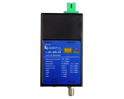
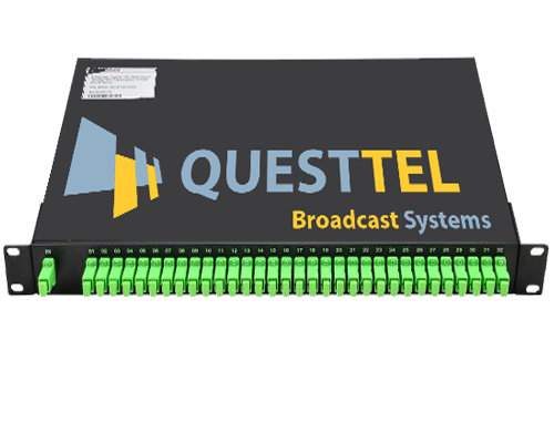
Plan a CATV RF-over-fiber network in one step. Enter how many optical receivers you need to
feed and how far away the farthest one is. The planner picks the smallest QuestTel transmitter or EDFA that
closes the link, sizes the PLC splitter, and shows the optical power and estimated carrier-to-noise ratio
(CNR) at every receiver.
Updated October 7, 2026 · Equipment figures from QuestTel datasheets
QuestTel shall have no liability for any error or damage of any kind resulting from the use of this
tool. Results are planning estimates from QuestTel datasheet values; confirm the design with an optical
power meter and signal-level meter at commissioning.
How to plan a CATV RF-over-fiber network
Count the receivers. Every building, floor or premises with its own optical
receiver takes one splitter output. Splitters come in powers of two, so 20 receivers need a 1x32.
Measure the longest run. The receiver farthest from the headend sees the most fiber
loss, so it sets the design.
Add up the losses. Subtract splitter insertion loss, fiber attenuation, connectors and
splices from the source's output power in dBm.
Check the receiver window. The power at each receiver has to sit inside its input range,
with margin above the minimum. Too much light overloads the receiver; an in-line
optical attenuator fixes that.
Check the CNR. Received optical power sets the carrier-to-noise ratio. Analog channels
need far more CNR than digital QAM, so the channel line-up decides how much light each receiver needs.
Transmitter or EDFA output, in dBm. P(dBm) = 10 × log10(P in mW).
L_split
PLC splitter insertion loss in dB; both stages for a cascaded split.
α
Fiber attenuation: 0.35 dB/km at 1310 nm, 0.22 dB/km at 1550 nm (cabled G.652.D).
d
Distance to the farthest receiver, in km.
N_c, N_s
Connector pairs and fusion splices end to end.
The design works when P_rx is at least the receiver minimum plus your margin, no higher than the receiver
maximum, and high enough to reach the CNR target.
For CNR, the planner starts from the point each QuestTel receiver is specified at: 45 dB at −10 dBm
for the L-RF-MN-RX and 51 dB at −2 dBm for the L-RF-19R-RX. It moves the CNR 1 dB for every 1 dB of
optical power and caps it at the transmitter's 51 dB rating. EDFA designs carry another 1 dB allowance for
amplifier noise. Treat the figure as a planning estimate: channel loading and modulation depth move the
real number, so confirm it with a meter at commissioning.
Worked example: 32 buildings at 8 km
A campus needs cable TV in 32 buildings. The farthest building is 8 km of fiber from the headend, the
line-up includes analog channels, and each building gets an L-RF-MN-RX mini receiver. There are 4 connector
pairs and 6 fusion splices end to end, and the design keeps 2 dB of margin. This is the planner's default
design.
Budget line
Value
L-RF-32mW-TX output, 32 mW
+15.1 dBm
1x32 PLC splitter, maximum insertion loss
−17.3 dB
Fiber: 8 km × 0.35 dB/km at 1310 nm
−2.8 dB
4 connector pairs × 0.5 dB
−2.0 dB
6 fusion splices × 0.1 dB
−0.6 dB
Power at each receiver
−7.6 dBm
−7.6 dBm sits 4.4 dB above the receiver's −12 dBm minimum, clearing the 2 dB margin, and gives
an estimated CNR of 47.4 dB against the 47 dB target for analog channels. The next size down, the 16 mW
transmitter, delivers −10.7 dBm: below the −10 dBm the margin requires, with an estimated CNR of
44.3 dB. So the smallest transmitter that works is the
L-RF-32mW-TX. With analog
channels it serves these 32 buildings out to 9.0 km; with an all-digital QAM line-up the CNR target drops to
35 dB and the same transmitter reaches 14.7 km.
How many receivers can each QuestTel source feed?
Maximum receivers per source by distance to the farthest receiver. The first figure is for a line-up with
analog channels (47 dB CNR target); the second is for digital QAM only (35 dB target). Assumes L-RF-MN-RX
receivers, datasheet-maximum splitter loss, 4 connector pairs, 6 splices and 2 dB margin. Counts are whole
splitter sizes; “—” means the source cannot reach even one receiver at that distance.
EDFA rows above +17 dBm assume the first splitter sits at the headend, so no single
fiber carries more than about +17 dBm (see 1310 nm or 1550 nm below).
Each doubling of transmitter power adds 3 dB. Doubling the split ratio costs about 3.4 dB on QuestTel
PLC splitters, so each step up the transmitter range roughly doubles the receivers it can feed until fiber
loss takes over.
Values include the SC/APC connectors on the splitter and hold from 1260 to 1650 nm, so the same splitter
works at 1310 nm and 1550 nm. Past 64 receivers the planner cascades two stages, for example a 1x4 feeding
four 1x32s for 128 receivers. More on how splitters and couplers work:
fiber optic couplers.
To hold a 47 dB CNR for analog channels, keep each L-RF-MN-RX at about −8 dBm or above and each
L-RF-19R-RX at about −6 dBm or above. Receivers close to the headend can get too much light; the
planner flags them and sizes an in-line attenuator.
What CNR does a CATV network need?
The FCC requires at least 43 dB carrier-to-noise for analog cable channels at the subscriber
(47 CFR §76.605).
Digital 256-QAM channels run reliably from about 31 dB. The planner adds 4 dB to each for the coax network
after the optical receiver, so it targets 47 dB for line-ups with analog channels and 35 dB for all-digital
line-ups. Going all-digital often lets one transmitter feed twice as many receivers. Channel plans:
CATV QAM channel center frequencies;
how QAM works: QAM constellation.
1310 nm transmitter or 1550 nm EDFA?
A directly modulated 1310 nm CATV
transmitter is the simplest fiber link: no amplifier, near-zero chromatic dispersion at 1310 nm, and up
to 32 mW (+15.1 dBm) of launch power. It suits campus, hotel, hospital, stadium and municipal networks out to
roughly 10–20 km with up to a few dozen receivers.
At 1550 nm, an erbium-doped
fiber amplifier (EDFA) goes further: fiber loss drops to about 0.22 dB/km and a 24 dBm EDFA delivers
251 mW, enough for hundreds of receivers. The EDFA needs a 1550 nm CATV transmitter driving it, at −5
to +10 dBm into the amplifier. Two cautions apply. Launch more than about +17 dBm into a single fiber and
stimulated Brillouin scattering degrades the signal, so high-power designs split at the headend first. And
analog signals at 1550 nm are sensitive to
chromatic dispersion, so
the transmitter driving the EDFA must be specified for 1550 nm CATV. Background on the two windows:
fiber
wavelengths and transmission windows.
Frequently asked questions
How many buildings can one CATV optical transmitter feed?
It depends on distance and the channel line-up. At 5 km with QuestTel L-RF-MN-RX receivers, a 32 mW
1310 nm transmitter feeds 32 receivers, and a 24 dBm 1550 nm EDFA feeds 128 receivers with analog
channels or 256 with digital QAM only. The table above covers 2 to 40 km.
What optical input power does a CATV receiver need?
Power inside the receiver's input window, with margin above the minimum: −12 to +3 dBm for the
L-RF-MN-RX and −9 to +2 dBm for the L-RF-19R-RX. To hold a 47 dB CNR for analog channels, keep each
L-RF-MN-RX at about −8 dBm or above and each L-RF-19R-RX at about −6 dBm or above.
Why does the planner round my receiver count up?
PLC splitters come in powers of two. Twenty receivers need a 1x32 splitter, and its insertion loss is
the same whether 20 or 32 ports are used, so the spare ports are free room to grow.
What if the optical power at a receiver is too high?
Too much light overloads the receiver and raises distortion. Fit an in-line SC/APC optical attenuator
on that receiver. The planner flags receivers close to the headend that would exceed the maximum and sizes
the attenuator.
Can RF over fiber carry digital QAM and ATSC channels?
Yes. The link is transparent to the RF it carries, so analog, QAM, ATSC and DVB-C channels from 45 MHz
up to 862 or 1003 MHz travel together. All-digital line-ups need far less CNR, which often lets one
transmitter feed twice as many receivers.
Should I plan with typical or maximum splitter loss?
Maximum, for a design that must work on every port. Typical loss is what most ports measure; use it
only to see how much headroom the finished network is likely to have.